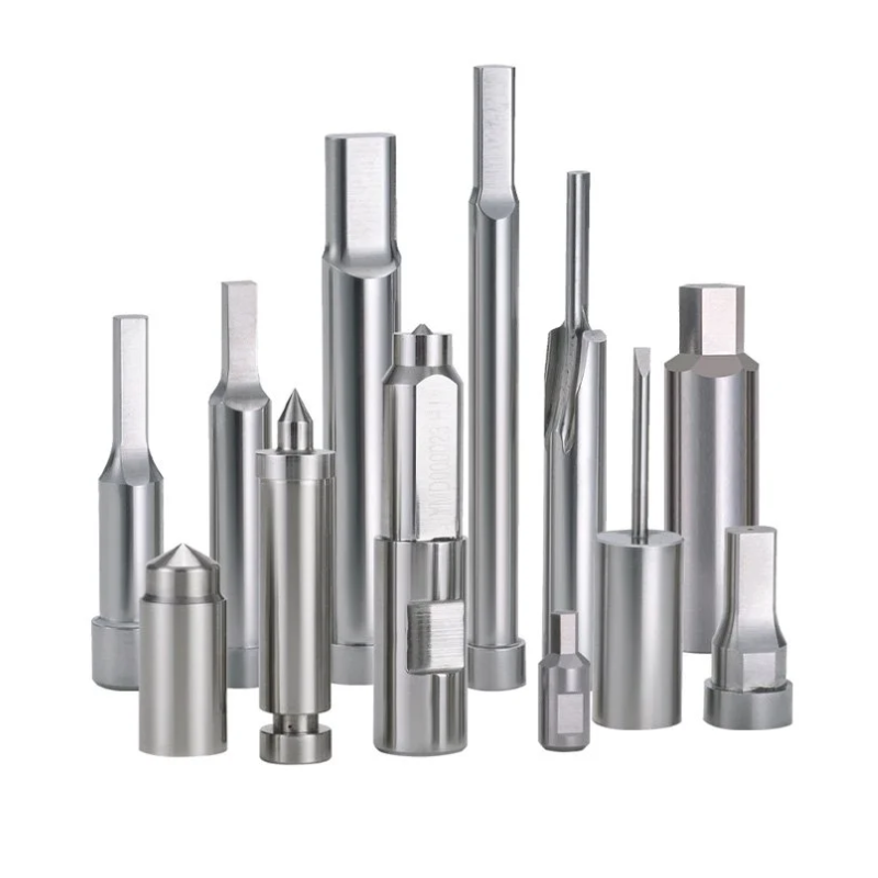
Punch clearance is one of those numbers that look simple on paper but cause real problems on the shop floor when it is wrong. Too tight, and you get excessive wear, galling, and punch breakage. Too loose, and you get burrs, poor edge quality, and dimensional variation. The right clearance lets the material shear cleanly through its thickness while keeping cutting force and tool wear under control.
Quick Answer: Clearance per side is estimated as material thickness multiplied by a clearance percentage. Total clearance is twice the per-side value. For piercing, the die opening equals punch size plus total clearance. For blanking, the punch dimension equals die opening minus total clearance. The correct percentage depends on material type, thickness, strength, operation, and required edge quality—not just one chart value.
What Is Punch Clearance?
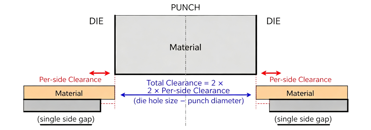
Punch clearance is the gap between the punch cutting edge and the die opening. It is usually described on a per-side basis, but the total clearance is what actually affects the punch and die dimensions.
If the clearance is 0.10 mm per side, the total difference between the punch and die is:
0.10 mm + 0.10 mm = 0.20 mm
This distinction matters because some charts and references list clearance per side, while others list total clearance. If you mix them up, your die opening can be off by a factor of two.
Key relationship: Total clearance = 2 × clearance per side
The clearance provides space for the material to deform, shear, and fracture as the punch enters the sheet. Without enough clearance, the material has nowhere to go. With too much, it fractures unevenly and leaves a rough edge.
How to Calculate Punch and Die Clearance
The basic starting calculation is straightforward: Clearance per side (C) = Material thickness (t) × Clearance percentage (k)
Then: Total clearance = 2 × C
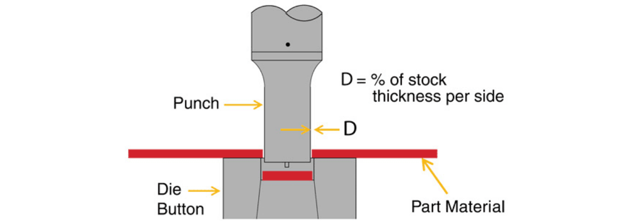
For a piercing operation, where the punch determines the finished hole size: Die opening = Punch size + Total clearance
Example: 1 mm Mild Steel, 10 mm Hole
Suppose you are piercing a 10.00 mm hole in 1.00 mm mild steel, and you select a starting clearance of 10% per side.
- Clearance per side: 1.00 × 10% = 0.10 mm
- Total clearance: 0.10 × 2 = 0.20 mm
- Punch diameter: 10.00 mm
- Die opening: 10.00 + 0.20 = 10.20 mm
This is the method. The actual production clearance should be confirmed against the material grade, thickness, tooling specification, and required edge quality. A 10% starting point works for many mild steel applications, but it is not a universal rule.
Piercing vs Blanking: Where Does Clearance Go?
The same clearance calculation applies differently depending on whether you are piercing or blanking. This is one of the most common sources of confusion.
| Operation | What Determines Finished Size | How to Apply Clearance |
|---|---|---|
| Piercing | The punch determines the hole size | Punch = required hole size; Die = punch + total clearance |
| Blanking | The die opening determines the blank size | Die = required blank size; Punch = die − total clearance |
For example, if you need a 50.00 mm blank and the total clearance is 0.30 mm:
- Die opening = 50.00 mm
- Punch dimension = 50.00 − 0.30 = 49.70 mm
If you apply the clearance the wrong way, the finished part will be oversized or undersized by the total clearance value.
The relationship between punch and die dimensions is central to die punch design. Getting the clearance direction right is just as important as getting the clearance value right.
Punch Clearance Chart by Material
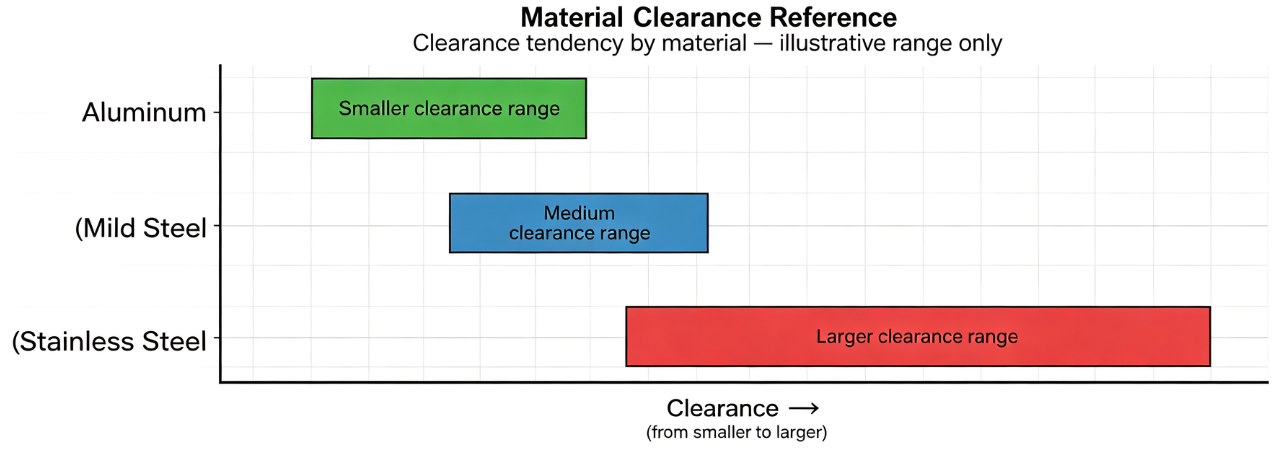
Clearance charts are useful starting points, but they are not universal specifications. Published charts can differ because they use different definitions (per side vs total), different material grades, different thickness ranges, and different assumptions about edge quality.
The table below shows example starting references for conventional stamping applications.
| Material | Example Starting Clearance | Notes |
|---|---|---|
| Aluminum | ~15% of material thickness | Softer material, lower shear strength |
| Mild steel | ~20% of material thickness | Common baseline for general stamping |
| Stainless steel | ~25% of material thickness | Higher strength, work-hardening behavior |
These values are reference points. Verify the actual clearance for your specific material grade, thickness, tooling, and edge-quality requirements.
Why Do Clearance Charts Show Different Values?
If two charts give different percentages for the same material, check these before assuming one is wrong:
- Is the percentage per side or total clearance?
- Are the material grades the same?
- Is the thickness range comparable?
- Are both charts for the same operation (piercing, blanking, etc.)?
- Do they assume the same edge quality requirements?
- Are the punch and die materials and tooling conditions similar?
For production tooling, treat the chart as a starting reference, not a final answer.
What Factors Affect Punch Clearance?
When punch and die clearance is too tight, the material requires more force to separate.
Possible effects include:
- Increased punching force
- Greater stress on the punch
- Accelerated punch and die wear
- Excessive burnishing
- Secondary shear or double shear
- Punch chipping or breakage
- Reduced tool life
A tight clearance may initially produce a smooth-looking edge, but the long-term cost is tool wear and unexpected breakage. If you are using HSS Punches in a tight-clearance operation, watch for chipping at the cutting edge. This is often a sign that the punch material selection is not matched to the application.
What Happens When Clearance Is Too Large?
Excessive clearance allows the material to fracture over a larger region, which produces a rougher edge and larger burrs.
Possible effects include:
- Larger burrs
- Rougher fracture surfaces
- Increased rollover
- Poorer hole-edge quality
- Dimensional variation
- Reduced tool life
Increasing clearance is not automatically good for tool life. The clearance needs to be balanced with the material and the required cutting quality.
How to Check Punch Clearance From the Slug
Slug inspection is one of the most practical ways to diagnose clearance problems without stopping production. The cut edge tells you what the clearance is doing.
A correctly selected clearance produces a predictable combination of a relatively smooth burnished zone and a rougher fracture zone. The ratio between them is a useful indicator.
| Condition | What You See on the Slug or Cut Edge |
|---|---|
| Clearance too tight | Large burnished area, increased cutting force, secondary shear, greater tool stress |
| Clearance too large | Smaller burnished area, larger fracture zone, pronounced burr, rougher edge |
| Clearance approximately correct | Balanced burnished and fracture zones, consistent edge, manageable burr |
Slug inspection is a diagnostic method, not an absolute measurement. Material properties, punch condition, die wear, and alignment can also affect the cut edge. Use it as one input, not the only one.
Punch Clearance Calculator: What Information Do You Need?
A basic clearance calculation requires six pieces of information:
- Material type and grade
- Material thickness
- Clearance percentage or reference value
- Punch size (for piercing) or die size (for blanking)
- Stamping operation
- Required hole or blank dimensions
The workflow is:
Material → Thickness → Clearance reference → Clearance per side → Total clearance → Punch and die dimensions
For a quick starting calculation:
Clearance per side = Material thickness × clearance percentage
Total clearance = 2 × clearance per side
Then apply the result to the correct component for your operation.
FAQ
How do I calculate punch and die clearance?
Clearance per side is material thickness multiplied by a clearance percentage. Total clearance is twice the per-side value. For piercing, die opening equals punch size plus total clearance. For blanking, punch size equals die opening minus total clearance.
Is punch clearance the same as die clearance?
In most contexts, punch clearance and die clearance refer to the same gap between the punch and die. The distinction is per-side versus total clearance, not punch versus die.
What clearance should I use for stainless steel?
Stainless steel typically requires a different clearance than mild steel because of its higher strength and work-hardening behavior. A starting reference around 25% of thickness is sometimes used, but the actual value depends on the grade, thickness, and operation.
How can I check clearance without measuring the punch and die?
Inspect the slug or cut edge. A balanced burnished zone and fracture zone suggests reasonable clearance. A large burnished area suggests tight clearance. A large fracture zone and heavy burr suggest excessive clearance.
How do I choose punch clearance for stainless steel?
Stainless steel clearance depends on the grade, thickness, hardness, and work-hardening behavior—not just the word “stainless.” A starting reference around 25% of material thickness is sometimes used, but 304 and 316 can behave differently, especially in high-volume stamping. Confirm the grade, thickness, clearance reference (per-side or total), and operation before finalizing. For high-volume stainless stamping, carbide or tungsten carbide punches are often preferred because they resist the wear caused by work-hardening.
Get the Right Punch for Your Clearance
Punch clearance only works when the punch itself is suitable for the material and operation. HTX Precision manufactures Punch Components in HSS, carbide, and tungsten carbide for different stamping conditions. For high-volume or abrasive applications, Carbide Punches and Tungsten Carbide Punches provide better wear resistance. For general stamping, HSS Punches offer a good balance of toughness and wear resistance.
If you are working on a stamping die and need help with punch selection, send us your drawing or application details. We will review the material, thickness, and operation and recommend the right punch for your clearance.