
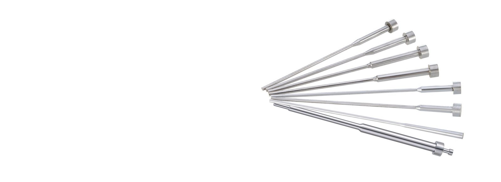
What Is a Step Ejector Pin?
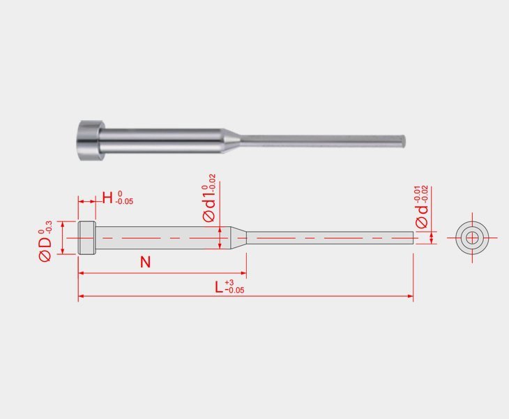
A step ejector pin is an injection mold ejector pin with two or more distinct diameter sections. It is also called a stepped ejector pin or shoulder ejector pin.
The stepped body allows the pin to control the ejection stroke height or position within the mold, unlike a standard straight ejector pin, for which a separate stroke limiter is often needed.
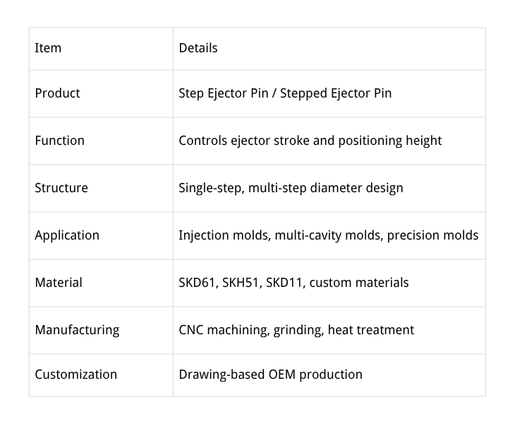
Why HTX Step Ejector Pins?
Step Ejector Pins deliver stable, controllable, and durable ejection strokes, making them suitable for precision plastic molds that rely on the pins themselves for positioning. It is also called the shoulder ejector pin.
During mold operation, are you troubled by issues such as inconsistent ejection height, unsynchronized ejection in multi-cavity molds, and premature wear of limiters? HTX strictly controls step height and concentricity to ensure stable and reliable ejection stroke performance; meets the specific requirements of multi-cavity molds and maintains uniformity; uses precision grinding processes to reduce wear; and supports highly repeatable custom designs, thus guaranteeing the long-term stable operation of the ejection mechanism.
If you require the ejector pin itself to control the stroke, the HTX Step Ejector Pin is your best choice.
Types of Step Ejector Pins
Step ejector pin/shoulder ejector pin provides reliable stroke positioning in multi-cavity molds, precision molds, and mold structures with strict restrictions on ejector height.
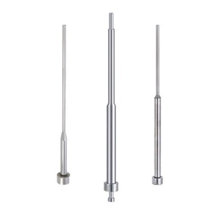
Features a single-step structure, suitable for multi-cavity molds and precision molds requiring basic stroke limitation, providing a reliable stroke control solution.
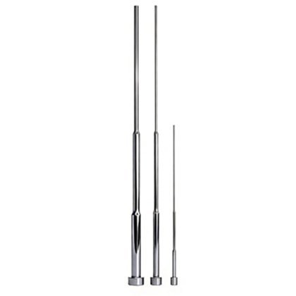
The multi-stage stepped design allows for segmented ejection, making it suitable for precision machining processes that require staged or variable-stroke ejection.
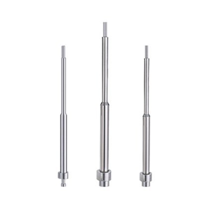
Supports customization of step height and diameter based on drawings to meet non-standard structures and special functional requirements, delivering high adaptability.
The Application of The Step Ejector Pins
The step ejector pins controlled the ejection length through the stepped design of the ejector pins themselves, which enhances mold stability and simplifies the assembly process.
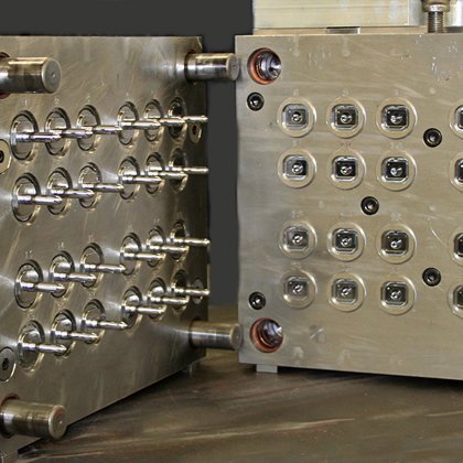 Multi-Cavity Injection Molds
The precise stroke control for the stepped ejector pins, it ensures that the ejection height is consistent across all cavities, preventing product height variations caused by asynchronous ejection and improving multi-cavity yield rates. It is widely used in plastic connectors.
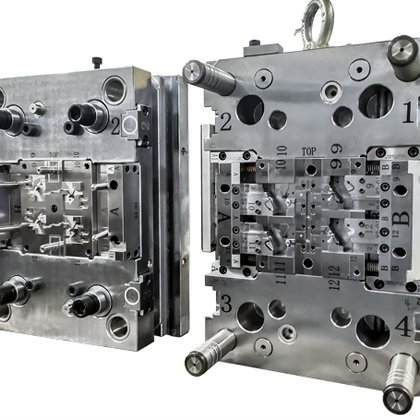 Precision industrial molds
This ejector pin precisely controls ejection distance through its stepped structure, preventing inconsistent ejection lengths or incomplete demolding to ensure consistent ejection dimensions. It provides stable positioning of the products.
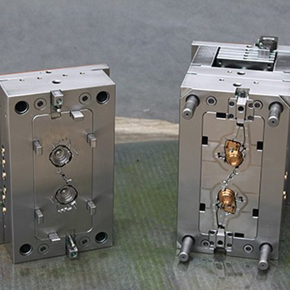 Thin-Wall Molds
Thin-wall cosmetic containers demand precise ejection control to prevent part deformation. Step ejector pins provide accurate stroke height, ensuring smooth release of delicate bottles, caps, and compact cases without surface marks.
 High-Cycle Molds
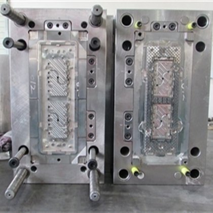
Automotive plastic parts run in high-cycle molds where ejection consistency directly impacts uptime. Step ejector pins maintain stable stroke control over millions of shots, supporting continuous production of connectors, housings, and interior components.
Customization of The Step Ejector Pins
The step ejector pin can be customized according to the drawing you provide. If you are unable to create a drawing, our professional engineering team can design suitable tolerances based on the drawings you provided. Once confirmed, we will arrange the sample production. Additionally, we maintain a large inventory of standard sizes for quick shipment. Please just provide your parameter to inquire about current stock availability.
How Does a Step Ejector Pin Work?
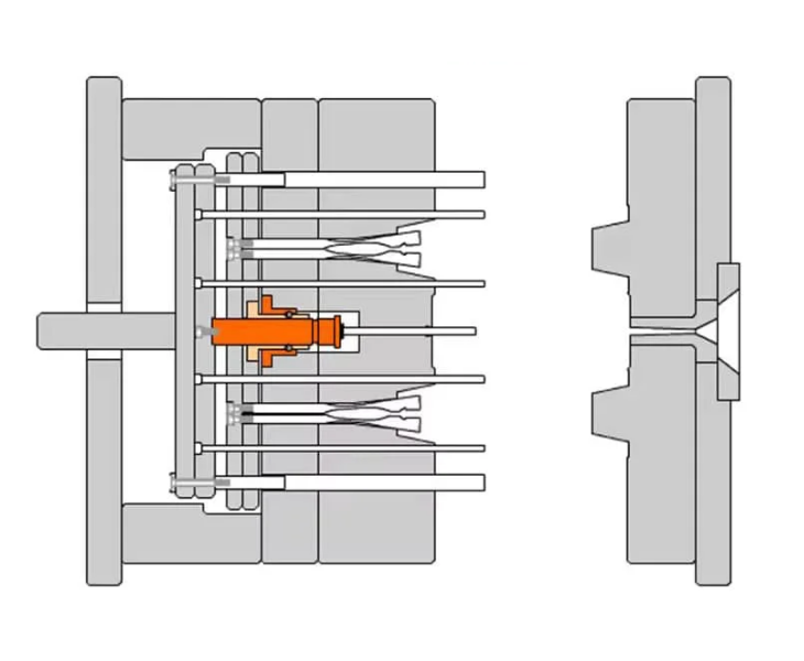
1. Mold closing
The step section contacts the mold plate or stopper.
2. Ejection movement
The ejector system pushes the pin forward.
3. Stroke limitation
The shoulder/step position controls the final ejection height.
4. Stable reset
The stepped structure helps maintain repeatable positioning.
| Problem | Cause | Solution |
|---|---|---|
| Uneven ejection height | Incorrect step tolerance | Precision grinding |
| Multi-cavity inconsistency | Different pin dimensions | Full dimensional inspection |
| Premature wear | Wrong material selection | Hardened tool steel |
Step Ejector Pin Manufacturing Process
Every step ejector pin is produced entirely in-house:
1. Material Selection
- Step ejector pins require high wear resistance and dimensional stability because they operate under repeated injection molding cycles. HTX selects tool steels such as SKH51, SKD61, and SKD11 according to mold requirements.
2.CNC Machining
Raw material is cut to length, then turned to form the preliminary stepped profile with grinding stock left on critical diameters.
3. Vacuum Heat Treatment
Vacuum hardening and tempering improve hardness and wear resistance while balancing surface hardness with core toughness. Minimal distortion ensures dimensional stability for precision grinding.
4. Precision Grinding
Precision grinding is the key process for creating the stepped diameter structure. The step height, diameter transition, roundness, and concentricity directly affect ejection stroke accuracy.
This process directly controls the ejection stroke accuracy—the step height tolerance and shank-to-step run-out are held to micron-level specifications.
5. Surface Treatment (Optional)
Nitriding, TiN, or DLC coatings can be applied for enhanced surface hardness, wear resistance, or anti-galling properties in demanding applications.
6. Final Inspection
Every batch is checked for diameter tolerance, step height, straightness, and surface roughness. Only pins passing all checks are released.
More You Need to Know About the Steped Ejector Pins
- Step Ejector Pin Structure
- Step Ejector Pin vs Straight Ejector Pin
- Standard Step Ejector Pin Dimensions
| Component | Function |
|---|---|
| Head | Connects with ejector plate |
| Large Diameter Section | Provides positioning control |
| Step Shoulder | Controls ejection stroke |
| Pin Tip | Contacts molded part |
| Precision Ground Surface | Ensures smooth movement |
For a detailed comparison of selection criteria and applications, see our guide: Step Ejector Pin vs Straight Ejector Pin.
| Feature | Step Ejector Pin | Straight Ejector Pin |
|---|---|---|
| Structure | Stepped diameter sections | Single diameter |
| Stroke control | Built-in step controls position | Requires external components |
| Suitable for | Precision molds requiring fixed stroke | General ejection applications |
| Design complexity | More customized | Standard design |
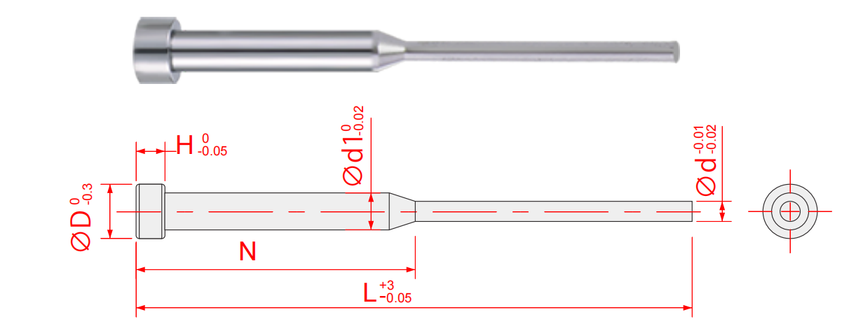
| Size:d1xNxdxL | |||||||||||||
| Length(L) | |||||||||||||
| Inch | 4″ | 6″ | 8″ | 10″ | |||||||||
| mm | 100 | 150 | 200 | 250 | |||||||||
| Rod Diameter(d1) Unit:(mm/Inch) | Rod Diameter(d) Unit:(mm/Inch) | (D) Head Diameter | (H) Head Thickness | ||||||||||
| mm | Inch | mm | Inch | mm | Inch | mm | Inch | ||||||
| 3 | 0.1181 | 0.8 | 0.0315 | 6 | 0.2362 | 4 | 0.1575 | ||||||
| 1 | 0.0394 | 0.2362 | 4 | 0.1575 | |||||||||
| 1.5 | 0.0590 | 0.2362 | 4 | 0.1575 | |||||||||
| 4 | 0.1575 | 2 | 0.0787 | 8 | 0.3150 | 6 | 0.2362 | ||||||
| 2.5 | 0.0984 | 0.3150 | 0.2362 | ||||||||||
A step ejector pin controls the ejection stroke length through its stepped structure, while a straight ejector pin lacks this limiting function. Want to know more about the straight ejector pin and the step ejector pin? Click here.
If you only have product images, we cannot provide customization. You must create corresponding 3D design drawings based on the plastic mold design of your product. Then we can process the pins according to these drawings.
The diameter change creates a mechanical stop that limits pin travel. Each step height is precision-ground to set a specific ejection distance.
Incorrect step height causing buckling, misalignment in the ejector plate, insufficient lubrication, and material fatigue in high-cycle applications.
Match step height to the required ejection stroke plus 0.5–1 mm safety margin. Confirm the shank diameter fits your ejector plate hole pattern.
Yes, the step ejector pins can be customized according to the drawing.
| Material | Characteristics |
|---|---|
| SKH51 | High hardness and wear resistance for high-cycle molds |
| SKD61 | Good toughness and heat resistance |
| SKD11 | Suitable for general precision mold components |
How To Choose a Step Ejector Pin?
Four decisions narrow down the right step ejector pin for your mold. Go through them in order.
1. Determine Mold Structure
Single-cavity or multi-cavity? Multi-cavity molds require consistent step heights across all pins to ensure uniform ejection. If your mold has multiple cavities, specify the same step height tolerance for the full set.
2. Select Material
High-cycle molds running millions of shots benefit from SKH51 high-speed steel for extended wear life. Standard production molds can use alloy tool steel. Match the material to your production volume, not just the plastic type.
3. Confirm Dimensions
Three dimensions define a step ejector pin: shank diameter, step diameter, and step height. Measure the ejector plate travel and cavity depth to determine each value. Undersized step height causes incomplete ejection; oversized risks mold damage.
4. Consider Tolerance
Precision molds demand tighter diameter and step height tolerances. Standard molds can accept broader tolerance bands. Decide early—tighter tolerances affect manufacturing lead time but prevent ejection inconsistency in high-precision applications.
Send your mold specifications for a step ejector pin recommendation →