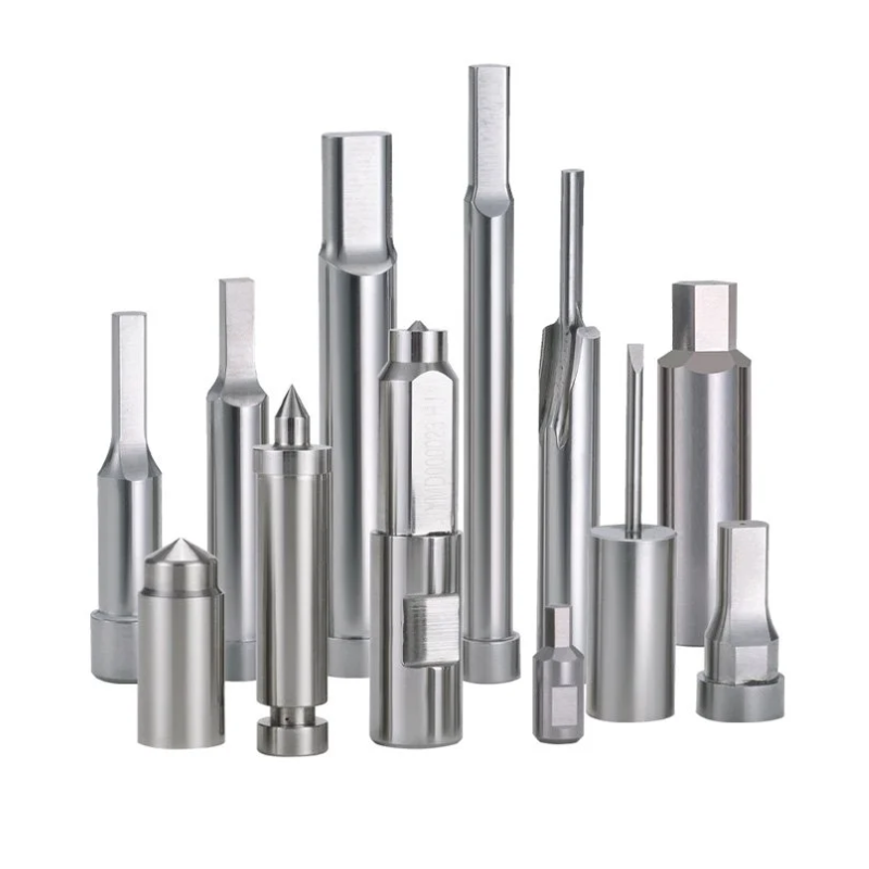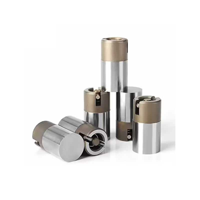
Choosing an ejector pin is not about picking a diameter. It’s about balancing ejection force, part geometry, and tool life. The right choice depends on how the part releases, not just how big the pin is.
First check draft, texture, and part release design. Then use the largest standard pin diameter that fits the local geometry. Distribute several pins evenly on ribs, bosses, and thick walls. Avoid thin walls and cosmetic surfaces. For tight ribs or thin sections, switch to blade or sleeve ejectors.
1. Start With Ejection Resistance, Not Pin Diameter
A larger pin cannot solve a problem created by poor release design. Before you choose a diameter, look at how much resistance the part will actually generate during ejection.
Shrinkage, draft, surface texture, core geometry, ribs, deep cores, material stiffness, packing, cooling, and vacuum all affect ejection resistance. If the part grips the core tightly, no reasonable pin diameter will eject it cleanly. You will simply transfer the problem to the pin—and end up with bending, breakage, or surface marks.
So the first step is not to select a pin size. The first step is to review the part design and ask: can this part be released without excessive force?
2. How Does Part Geometry Affect Ejector Pin Size?
Part geometry controls where pins can be placed and how much load each pin will carry. Wall thickness, ribs, bosses, flanges, and deep cores all influence the decision.
There is no universal formula that says “a wall thickness of X mm requires a pin of Y mm.” That approach fails because the ejection force is not distributed evenly. A thick wall may allow a large pin, while a thin rib may need a blade or a small step pin.
Start by identifying the strongest structural features on the part. These are the areas that can accept ejection force without deforming. Ribs, bosses, and thick flanges are usually better candidates than thin walls or cosmetic surfaces.
3. How Does Ejection Force Affect Pin Diameter?
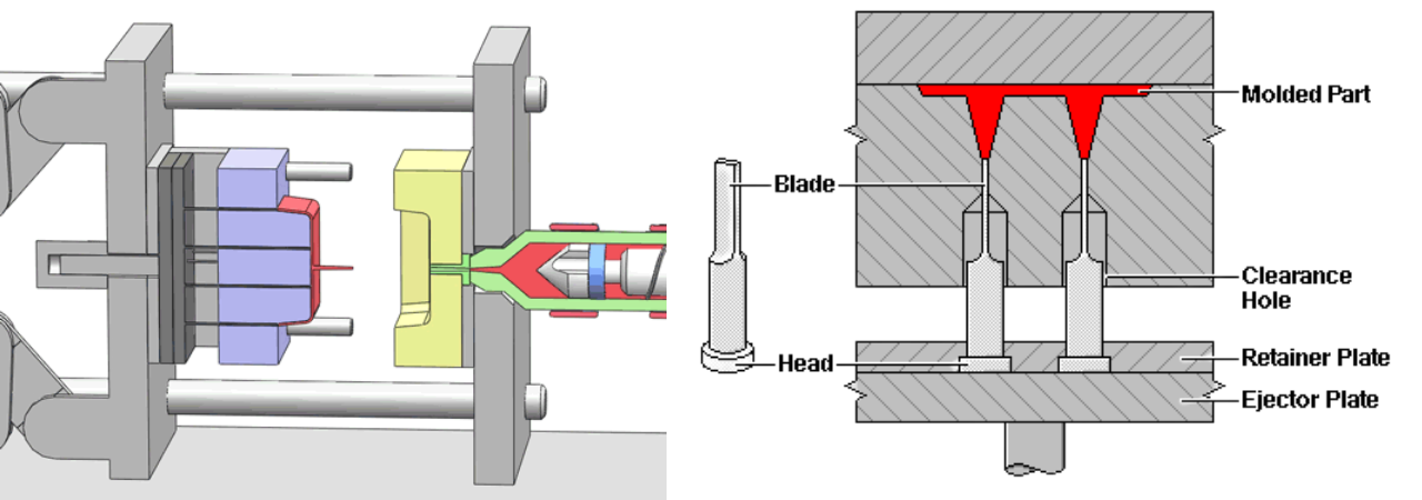
Ejection force equals average contact pressure times effective contact area. Increasing pin diameter increases local contact area. Increasing pin quantity increases total effective ejection area.
But actual pressure is not uniform. Part stiffness, friction, and local support all change the real distribution. A pin in a stiff boss area may carry much more load than one on a flexible wall. So diameter selection must follow the load path, not just the available space.
When you estimate the required ejection area, do not assume every pin shares the load equally. Add margin by using more pins or larger diameters in high-resistance areas.
4. How to Select Ejector Pin Diameter
Use the largest practical standard diameter. But “practical” means the largest size that fits within the local part geometry and the mold structure—not just the biggest size available.
Go through these five checks before settling on a diameter:
- Local geometry: Can the pin physically fit at the ejection point without breaking through a thin wall or rib?
- Contact area: Does the pin face provide enough area to avoid excessive local stress on the part?
- Ejector mark: Is the pin mark acceptable on the visible surface? Larger pins leave larger marks.
- Support: Will the pin be guided properly along its length? A large diameter in a poorly guided bore still bends.
- Standard size: Can you use an off-the-shelf diameter and length? Custom pins cost more and extend lead time.
If all five checks pass, you have your diameter. If not, adjust the pin type, position, or number of pins before forcing a larger diameter into a tight area.
5. Ejector Pin Diameter vs Buckling Risk
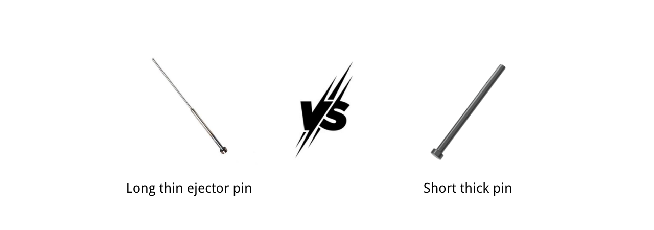
Bending stiffness increases with the fourth power of diameter. Doubling the diameter makes the pin roughly 16 times stiffer. But pin length matters too. An unsupported long section behaves very differently from a short, well-guided pin.
A small-diameter pin is not automatically the wrong choice. If it is short and well guided, a 2 mm pin can be perfectly reliable. A long 4 mm pin without intermediate guidance can still buckle.
So when you evaluate buckling risk, look at the unsupported length and the guidance arrangement, not just the diameter. A step pin can help by keeping a larger diameter in the unsupported section, but it cannot replace proper guidance.
6. How Many Ejector Pins Does a Mold Need?
There is no universal spacing rule. Required ejection area, part stiffness, resistance, and available locations together determine how many pins are needed.
If the part is stiff and the release force is low, a few well-placed pins may be enough. If the part is thin, flexible, or has high shrinkage, you will need more pins to distribute the load and avoid local deformation.
Think in terms of total effective ejection area. The total area is the sum of all pin contact faces. You can increase total area by using more pins or larger diameters. But more pins also mean more holes, more wear points, and more potential for flash or alignment issues.
Start with the minimum number of pins that satisfies the required ejection area and part support. Then add more only where the part shows a tendency to stick or deform locally.
7. Where Should Ejector Pins Be Placed?
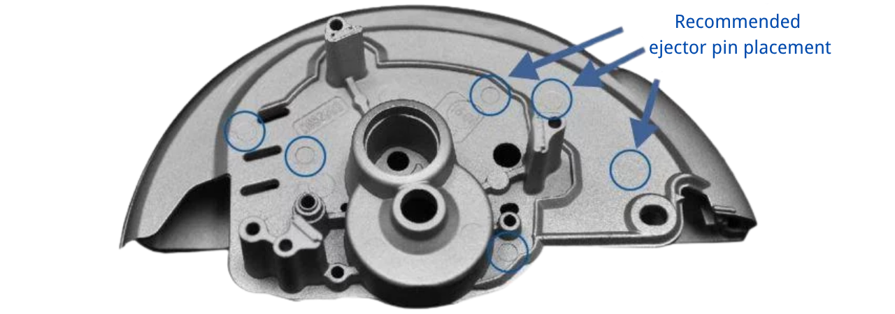
Place pins on ribs, bosses, thick walls, flanges, and other high-resistance areas. These are the locations where the part needs the most support during ejection.
Avoid cosmetic surfaces, unsupported thin walls, and weak corners. A pin on a thin wall can push through the part or leave a visible mark. A pin on a weak corner can cause cracking or white stress marks.
Advanced mold designers do not place pins simply by geometric symmetry. They follow the load path. The load path is the route through the part that transfers ejection force from the pin to the rest of the part without causing bending or distortion.
For example, a deep rib may need a blade ejector rather than a round pin, because the rib can only accept a narrow line of contact. A boss may need a sleeve ejector to push around its full circumference. Placement and type must work together.
8. Does Draft Angle Affect Ejector Pin Selection?
Yes. Increasing draft angle reduces friction and ejection resistance. That means the part needs less ejection force, so you may be able to use fewer or smaller pins.
Before adding pins or increasing diameters, check whether the draft can be improved. A change from 0.5° to 1.5° on a deep core can dramatically reduce the force required to release the part. In many cases, the pin problem disappears once the draft is corrected.
The sequence should always be: fix the release design first, then select the ejector system. If you do it the other way, you end up with larger pins than necessary, more visible marks, and higher mold cost.
9. How Do I Choose Between Straight, Stepped, Blade and Sleeve Ejectors?
Different part features require different ejector types. Use the table below to match the feature to the effective solution.
| Type | When to Use | Internal Link |
| Straight pin | General solid surfaces | Straight Ejector Pin |
| Stepped pin | Small tip + larger supporting shaft | Step Ejector Pin |
| Blade ejector | Narrow ribs | Blade Ejector Pin |
| Sleeve ejector | Cylindrical bosses | Ejector Sleeve |
If you are not sure which type fits your part, send us the drawing. We will review the geometry and recommend the type that gives the cleanest ejection with the least tool wear.
10. How Does Plastic Material Affect Ejector Pin Selection?
The resin affects shrinkage, adhesion, stiffness, and thermal behavior. These factors change how much force is needed and how the pin interacts with the part.
Glass-filled materials are abrasive. They wear ejector pins faster, especially at the tip. For high-wear applications, select a pin with surface hardening or coating.
Soft materials, such as TPE or soft PP, deform easily under local load. Use larger contact areas to reduce pin marks and prevent puncturing the part.
High-shrinkage resins, such as unfilled PP or PE, grip the core more tightly during cooling. They need higher ejection force or better release features, not just more pins.
So do not simply choose the pin based on the part material name. Look at the specific material behavior: how much it shrinks, how stiff it is at ejection temperature, and how abrasive it is in the mold.
11. Ejector Pin Material and Surface Treatment
Material choice is as important as diameter. Hardness alone does not guarantee good performance. A very hard pin can be brittle and snap under side load.
The table below summarizes the most common material and treatment options for ejector pins.
| Material / Treatment | Why Use It |
| SKD61 | General purpose |
| SKH51 | High wear resistance |
| Nitrided SKD61 | Surface hardness + tough core |
| TiN / DLC coating | Friction reduction, anti-galling |
For small tip diameters below 2 mm, we usually recommend SKD61 or nitrided SKD61 rather than SKH51. The extra toughness is more valuable than a few extra points of hardness. For large, well-supported pins in abrasive materials, SKH51 can be a good choice.
Surface treatment should be matched to the wear mechanism. If the pin wears on the tip from contact with the part, nitriding helps. If the pin galls inside the bore, a TiN or DLC coating may be more effective.
12. Clearance, Guidance and Mold Tolerance
Even the best pin will fail if the hole is not properly sized. Pin-to-hole clearance, guidance length, alignment, and thermal expansion all affect performance.
Clearance that is too tight causes galling and sticking, especially at elevated mold temperatures. Clearance that is too loose allows flash and misalignment, which leads to side wear and bending.
The exact clearance depends on the pin diameter, length, material, and mold temperature. We do not use a single “standard” clearance for every mold. Instead, we recommend application-specific tolerances during design review.
Pay attention to the transition in a step pin. If the bore does not match the step properly, the pin will misalign and wear quickly. The step is a precision feature, not just a cosmetic difference.
13. Common Ejector Pin Selection Mistakes
Most ejection failures can be traced back to one or more of these mistakes.
| Mistake | Engineering Consequence |
|---|---|
| Pin too small | Bending / breakage |
| Too few pins | Local deformation |
| Too many pins | Unnecessary marks/machining cost |
| Poor placement | Uneven ejection |
| Ignoring draft | Excessive ejection force |
| Ignoring pin length | Buckling risk |
| Wrong material | Wear/failure |
| Excessive hardness without toughness | Brittle failure risk |
If you have encountered bending, flash, or part distortion during ejection, check this list first. Most problems are caused by one of these factors, not by the pin itself.
14. Practical Ejector Pin Selection Workflow
Here is a step-by-step workflow we use when reviewing a new mold design. It takes you from the part drawing to final DFM validation.
Part Drawing → Ejection Resistance → Part Support Areas → Required Ejection Area → Pin Type → Diameter → Quantity → Placement → Length & Buckling Check → Material / Treatment → Clearance / Guidance → DFM Validation
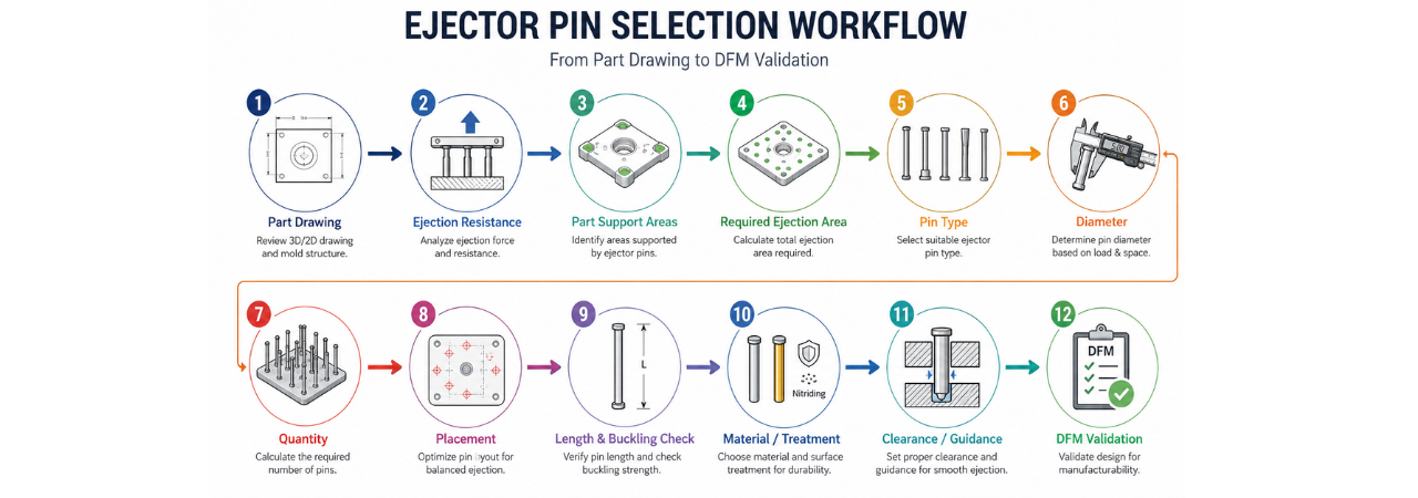
Follow this flow, and you will end up with a pin layout that balances ejection force, part quality, and mold longevity.
FAQ
Does a larger ejector pin always provide better ejection?
No. A larger pin increases the ejection area but also leaves a larger mark and may not fit in the available part geometry. The best pin is the largest practical diameter that meets the local constraints, not simply the biggest available.
How does ejector pin length affect the required diameter?
A longer pin is more prone to buckling, so it may need a larger diameter or additional guidance. However, a longer pin does not automatically require a larger diameter if the pin is well supported along its length.
Can ejector pin placement cause part deformation?
Yes. Placing a pin on a thin wall, unsupported area, or weak corner can push through the part, create visible stress marks, or cause local cracking. Always place pins on ribs, bosses, or thick structural sections.
When is a blade ejector better than a round ejector pin?
Use a blade ejector when the part feature is too narrow for a round pin, such as a thin rib. A blade provides a line of contact instead of a point, reducing local stress and fitting into tight geometries.
Get Your Ejector Pin Selection Right
Send us your part drawing or 3D file. HTX engineers will recommend pin size, type, and layout—free. We will review the ejection resistance, support areas, and material to give you a practical, production-ready layout.