If you design or maintain injection molds, you’ve probably faced this problem: The part has a small rib, boss, or narrow feature, and a standard straight ejector pin won’t fit. You could reduce the whole pin diameter, but then it bends during ejection. That’s exactly when a step ejector pin starts to look like the right answer. But is it always the better choice? Not necessarily.
In this guide, we’ll show you when a step ejector pin makes sense, when a straight pin is still the better option, and how to avoid the most common failures.
What’s a Straight Ejector Pin?
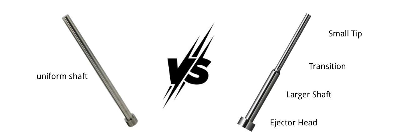
A straight ejector pin has a uniform diameter along its entire length. It is the standard choice for general injection molding applications where ejection force is evenly distributed, and no special stroke control is required.
What Is a Step Ejector Pin?
A step ejector pin features two or more diameter sections along its body. The stepped design adds mechanical strength for long or thin pins, and the shoulder can act as a stroke stop for controlled ejection in precision or multi-cavity molds.
What’s the Real Difference?
A straight ejector pin and a step ejector pin both push the part out of the mold—but their geometry leads to different strength, precision, cost, and application profiles. Understanding these differences helps you avoid over-specifying or under-designing the pin.
1. Structural Geometry
A straight ejector pin has a single diameter from tip to head. If the ejection point is 3 mm, the entire working section is built around that 3-mm diameter. A step ejector pin has two or more diameters: a small tip transitions into a larger support shaft, then into the ejector head. This is the primary difference, but it’s not just about looks—it directly influences everything below.
2. Strength and Rigidity
A straight pin with a small diameter is weak across its entire length, making it prone to bending under load or during ejection. A step pin solves this by pairing a small ejection tip with a larger support shaft. However, a step pin is not automatically stronger than a straight pin—a large-diameter straight pin can be far stiffer than a small step pin. The step design’s real advantage is that it allows a small contact face without sacrificing the rigidity of the main shaft.
3. Application Suitability
Straight pins work well when the ejection area is large enough to allow a full-diameter pin, loads are moderate, and ejection is uniform. Step pins excel in tight spaces, thin ribs, deep pockets, or high-stress areas where a small ejection face is required but bending resistance is critical. They are common in precision molds, small-part tooling, and multi-cavity layouts.
4. Ejection Precision and Stroke Control
A straight pin usually relies on the ejector plate for stroke control, and all pins share the same travel. A step pin’s shoulder can act as a built-in mechanical stop, giving you independent stroke control for that pin. This allows sequential ejection—some pins push first, others follow—which is valuable for complex parts with multiple release points.
5. Cost and Manufacturability
Straight pins are simple to machine, widely available as standard components, and cost less. Step pins require additional turning, grinding, and heat treatment steps, making them more expensive and often custom-manufactured. However, the higher upfront cost can pay back through longer tool life and fewer molding defects in demanding applications.
6. Maintenance and Replacement
Standard straight pins are easy to stock and replace quickly during mold maintenance. Step pins, being custom or semi-custom, have longer lead times and may require careful handling to protect the step transition from damage. On the flip side, a well-designed step pin often wears more evenly at the ejection tip because the larger shaft resists bending that would otherwise cause side wear.
Choose a straight pin when geometry allows it and cost is a priority. Choose a step pin when you need a small ejection face with better support, independent stroke control, or bending resistance in difficult areas. If you’re unsure, provide your mold layout—our engineers will recommend the right configuration.
Why Straight Pins Are the Default Choice?
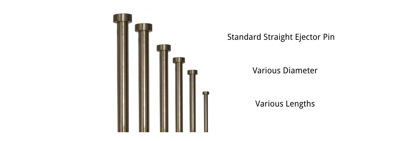
In most molds, a straight ejector pin should be your default choice. It is simpler to machine, easier to fit, easier to replace, more standardized, and less expensive than a step pin. If the ejection area allows a standard diameter and the pin length is reasonable, there’s no need to complicate the design. A step pin introduces an extra machined feature and a potential stress point, so if you don’t need it, don’t add it. Our rule is simple: use a straight pin unless the part geometry requires a different approach.
When a Step Pin Is Worth It?
You should consider a step ejector pin when one or more of these conditions apply:
- The ejection point is too small for a standard straight pin
- A small-diameter straight pin would be too long and flexible
- You need different diameters along the pin to fit the mold space
- The part has a small boss or rib that must be ejected but can’t accept a larger pin mark
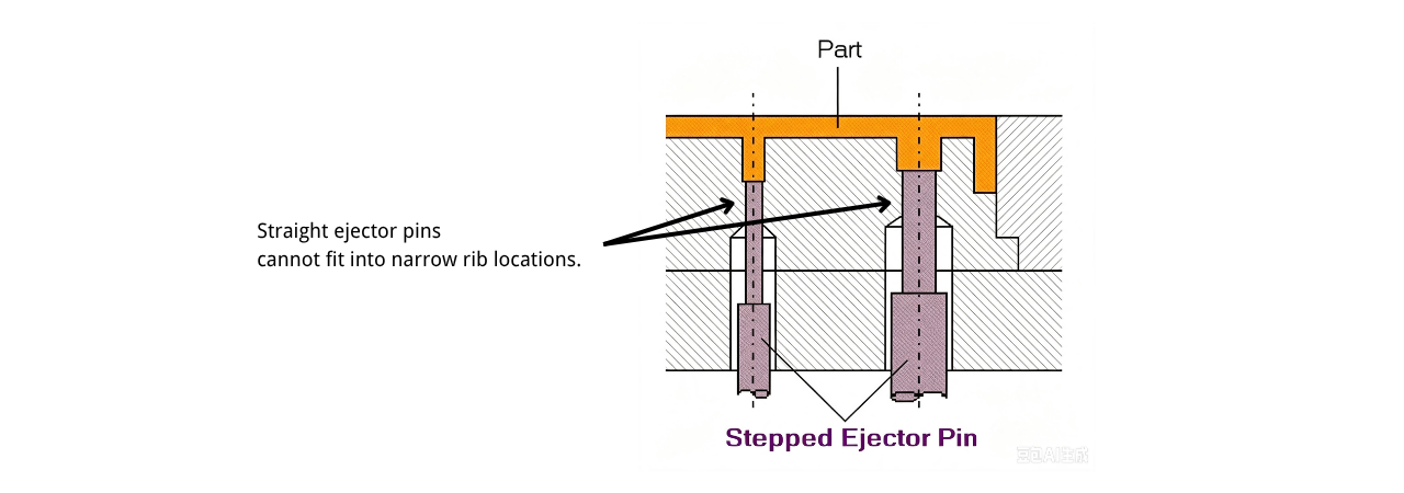
For example, you may have a deep rib that is only 2.3 mm wide.
A 2.5 mm straight pin won’t fit.
A 2 mm straight pin at 90 mm long will almost certainly bend under ejection load.
That’s where a 2 mm tip / 4 mm shaft step pin solves the problem.
This is a common situation, not an unusual one.
If you work on consumer products, automotive interiors, or precision electronic housings, you will meet this case sooner or later.
Bending Resistance: Why Diameter Matters More Than Shape?
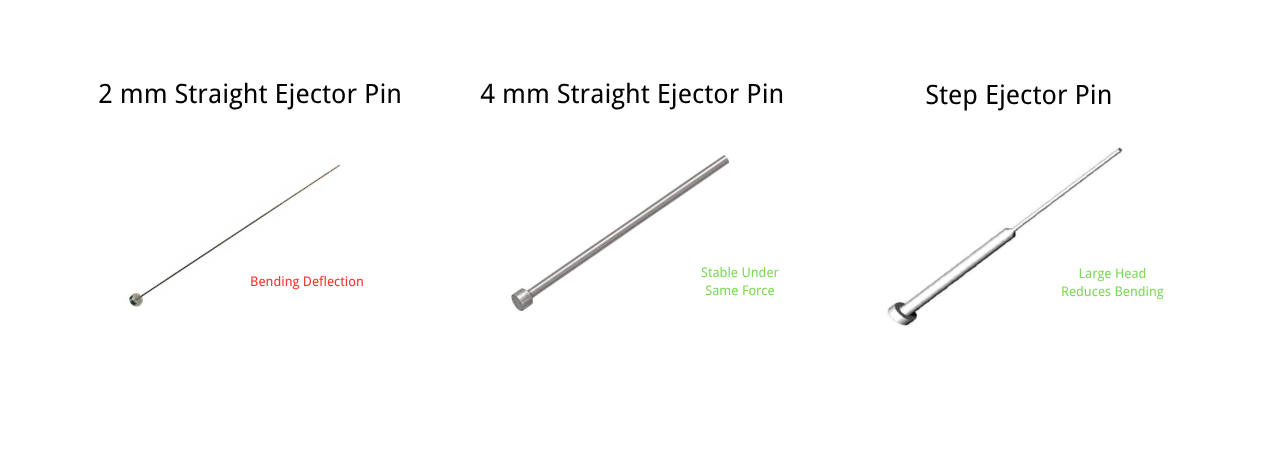
When you’re trying to prevent bending, diameter is the main factor—not pin shape. Bending stiffness scales with the fourth power of diameter. So if you reduce a pin from 4 mm to 2 mm, you’re not making it half as stiff; you’re making it roughly 16 times more flexible.
This is why a long 2 mm straight pin is risky. A step pin helps only because it lets you keep a larger diameter where most of the unsupported length is. The step shape itself doesn’t add stiffness—it simply allows the larger diameter to be there.
Changing from a straight pin to a stepped pin without increasing the main shaft diameter will not improve bending resistance. The step only works when the larger section actually carries the load.
But even a stepped pin won’t save a slender design if the small tip section is too long or unsupported. Diameter still rules. You need to check unsupported length, clearance, and ejection force direction, and make sure the large-diameter section is supporting the pin where it matters.
How to Choose: A Practical Checklist
Choosing between a straight and step ejector pin isn’t just about checking a few boxes. It’s about matching the pin to the actual ejection conditions. Below are the key dimensions we look at, with practical guidelines you can apply directly to your mold design.
1. Available Ejection Area
Start by measuring the actual contact face on the part where the pin will push.
If the area is large enough to fit a standard straight pin of 3 mm or larger, a straight pin is usually the simplest and most economical choice.
If the available face is below 2.5 mm, a straight pin may be too weak. This is where a step pin starts to make sense, using a small tip while keeping a larger support shaft.
For very small tips below 1.5 mm, even step pins become risky. You may need additional guidance or a different ejection method.
Rule of thumb: If the ejection point is smaller than 2.5 mm, evaluate the step option. If it’s smaller than 1.5 mm, question whether a pin is even the right solution.
2. Pin Length and Slenderness Ratio
Pin length has a major influence on bending. The key number is the length-to-diameter ratio (L/D) of the smallest section.
For a straight pin, if L/D is below 30, bending is usually manageable with proper clearance.
For L/D between 30 and 60, bending becomes a real risk, especially with small diameters.
Above L/D of 60, a straight pin is rarely reliable without a guide bush or stepped design.
A step pin helps because the larger shaft reduces the effective L/D of the main supporting section. But the small tip still has its own L/D, and that tip section must be kept short.
Practical check: Calculate L/D for the smallest section. If it exceeds 40, consider a step pin or add a guide.
3. Load Direction
Ejection force is rarely perfectly axial. Many pins push on angled surfaces, ribs, or textured areas, creating a side load component.
If the load is mostly axial, a straight pin is fine.
If there is a noticeable side load, a straight pin with a small diameter will flex and wear unevenly.
A step pin provides more resistance to this side load because of the larger supporting shaft, but it still requires proper clearance.
Tip: If you’re ejecting from an angled surface, don’t rely on a small straight pin. Increase the diameter or use a step pin and add a guide bush.
4. Guidance and Support
A pin is only as good as the bore that guides it.
A straight pin is guided by the ejector plate hole and the core hole. For long pins, an intermediate guide bush is often needed.
A step pin needs accurate alignment of the step and the bore transition. Misalignment here causes early wear or bending.
Check the unsupported length between the ejector plate and the first guide point. If it’s too long, the pin will bend regardless of its diameter.
Practical rule: If the unsupported length is more than 3–4 times the pin diameter, add a guide or step design.
5. Material and Surface Treatment
Material selection should match the load and wear conditions, not just the pin type.
For moderate loads and short runs, SKD61 is a balanced choice.
For high wear or high-temperature molds, SKH51 can be considered, but it is more brittle. Avoid it for small tip diameters below 2 mm.
For long production runs or abrasive resins, nitriding the tip of an SKD61 step pin improves wear resistance without sacrificing core toughness.
Guideline: If the tip diameter is 2 mm or less, we generally recommend SKD61 or SKD61 + nitriding. SKH51 is acceptable for larger diameters where toughness is less of a concern.
| Comparison Item | SKH51 | SKD61 | SKD61 + Nitriding |
| Material Type | High-speed steel | Hot work tool steel | Hot work tool steel + surface nitriding |
| Typical Hardness | 58–60 HRC | 50–55 HRC | Surface: approx. 900 HV or above; core: 40–45 HRC |
| Wear Resistance | High | Moderate | High on surface, moderate in core |
| Toughness | Lower; small-diameter tips may be prone to brittle fracture | Better; good impact resistance | Core remains tough; surface hardened |
| Bending Resistance | Depends on diameter; high hardness but relatively brittle | Good toughness; more suitable for slender pins | Surface hardness improved; overall bending resistance changes little |
| Heat Resistance | Good | Good; better thermal fatigue resistance | Improved surface heat and wear resistance |
| Nitriding Suitability | Generally not preferred or less common | Commonly used; good results | Recommended |
| Suitability for Small-Diameter Step Pins | Use with caution, especially below 2 mm tip diameter | More suitable | Preferred |
| Cost | Generally higher | Moderate | Slightly higher than non-nitrided SKD61 |
But here’s a detail many designers miss: The tip diameter usually controls nitriding depth on a step pin.
That means the larger shaft behind the tip may not have the same surface hardness. If you need wear resistance along the full length, you must confirm this with your supplier. We’ve seen pins ordered as “nitrided” where the shaft wore faster than expected. This wasn’t a supplier error. It was a design detail that was easy to overlook.
6. Ejector Mark and Appearance
The ejector mark left on the part may be visible or functional.
A larger pin face leaves a larger mark. If the mark is on a cosmetic surface, the design must minimize it.
A step pin allows a smaller tip, which reduces the visible mark while still providing strength behind it.
If the part has strict appearance requirements, consider using a small step pin tip or an alternative ejection method like a blade ejector.
Check: Does the customer accept the size of the ejector mark? If not, a step pin with a smaller tip may be required.
7. Cost and Maintenance Considerations
Straight pins are cheaper and easier to stock. Step pins cost more and often require custom manufacturing. But the higher cost may be justified if it prevents mold downtime or part defects.
For low-volume molds, the cost difference may not matter. Use the simpler option.
For high-volume molds, the long-term reliability of a step pin can pay for itself.
Consider replacement lead time. Standard straight pins are off-the-shelf; custom step pins take longer.
Decision point: If the mold will run millions of cycles, invest in the pin design that reduces maintenance. If it’s a prototype or short-run mold, keep it simple.
Final Selection Flow
Here’s a simple sequence we use in practice:
Can a straight pin of at least 3 mm fit? If yes, use it.
If not, can a straight pin of smaller diameter survive the length and load? Check L/D and side load.
If a smaller straight pin is too weak, use a step pin with a larger support shaft.
If the tip is below 1.5 mm, reconsider the ejection method or add special guidance.
Choose material based on tip diameter, load, and expected cycle life.
If you follow these steps, you’ll avoid the most common ejection failures and choose the right pin for the job.
FAQ
1. What causes step ejector pins to fail?
Step ejector pins don’t fail just because they have a step. The most common causes are:
- Excessive side load or off-axis ejection force
- Long unsupported length without proper guidance
- A sharp transition at the diameter change
- Insufficient clearance or poor surface finish
- A brittle material at a small tip diameter
Among these, the transition is one of the most important areas. If it’s left as an abrupt corner, it becomes a stress raiser. A properly ground transition with a smooth radius reduces that risk. In practice, bending and wear are the two most common long-term failure modes. Breakage is usually a combination of small tip diameter, brittle material, and poor transition geometry.
2. Can I replace a straight ejector pin with a step ejector pin in an existing mold?
It’s possible, but not always a direct replacement.
You need to check the step position, tip diameter, guide clearance, and head dimensions before making any substitution.
3. Are step ejector pins stronger than straight ejector pins?
Not automatically.
A step pin’s advantage is that it lets you use a smaller tip with a larger supporting shaft.
Actual strength depends on diameter, unsupported length, material, and guidance.
4. What material is best for step ejector pins?
There is no single best material.
SKH51 is good when high hardness and wear resistance are priorities.
SKD61, especially with nitriding, is often better for small tip diameters because it offers better toughness.
5. How can I prevent step ejector pin bending or breakage?
Use a properly ground transition, provide adequate guidance, keep the load as axial as possible, and select a material with enough toughness for the tip diameter.
6. Can step ejector pins be custom made?
Yes. Custom step pins can be manufactured to your tip diameter, shaft diameter, step position, length, material, hardness, and surface treatment requirements.
Final Thoughts
Step ejector pins and straight ejector pins are not two versions of the same thing.
They solve different problems.
If you can use a straight pin, use it.
It’s simpler, cheaper, and easier to maintain.
If your part geometry forces a small ejection point and a longer pin length, a step pin is often the right solution.
Just pay attention to the transition, the guidance, and the material.
At HTX Precision, we manufacture custom step ejector pins and straight ejector pins for injection mold applications.
We work with tip diameters from 1.0 mm to 25 mm, and we can match your required hardness, nitriding, and surface finish.
Send us your drawing, and we’ll help you choose the right ejector pin configuration for your mold.