
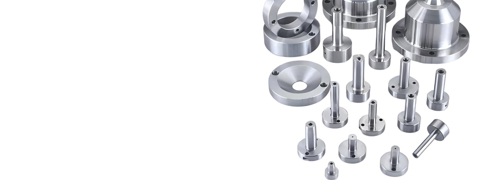
What is a Sprue Bushing?
A sprue bushing, also called a sprue bush, is a precision mold component installed at the injection entrance of an injection mold. It provides the connection between the injection molding machine nozzle and the mold’s sprue or runner system.
Its internal passage guides molten plastic from the nozzle into the mold, while its nozzle-contact geometry helps maintain proper alignment and sealing.
HTX Precision supplies A-Type, B-Type, and C-Type sprue bushings, with selected standard dimensional configurations and drawing-based customization.
The sprue is the primary passage through which molten plastic enters the mold from the injection nozzle. The sprue bushing forms the inlet component around this passage.
What Does a Sprue Bushing Do?
A sprue bushing performs several functions at the injection entrance of an injection mold. It connects the injection nozzle to the mold, guides molten plastic into the sprue and runner system, and helps maintain proper nozzle contact and alignment.
The sprue bushing serves as the physical and thermal interface between the injection molding machine nozzle and the mold base. Mounted in the center of the mold’s fixed half, its inlet aligns with the nozzle tip to receive molten plastic. The bushing’s body extends through the mold plate, creating a direct channel that ensures material enters the mold at the correct location and temperature.
The sprue bushing directs molten plastic from the injection nozzle through the sprue, and then into the runner system. From the runner, the material flows through the gate and finally fills the mold cavity. This controlled pathway ensures consistent material flow and minimizes turbulence during the injection cycle.
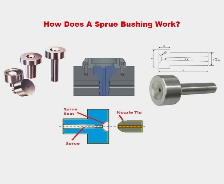
The sprue bushing maintains proper contact with the injection nozzle to prevent plastic leakage and pressure loss. The SR (Spherical Radius) on the bushing inlet matches the nozzle radius, creating a tight seal that keeps molten material contained within the system. This sealing function is critical for maintaining consistent injection pressure and preventing flash defects on finished parts.
The sprue bushing creates a precisely controlled entrance to the mold’s runner system. By optimizing the sprue’s taper angle and surface finish, the bushing reduces pressure drop and facilitates smooth material transition into the runner. This design consideration directly impacts cycle time, part quality, and overall molding efficiency.
Sprue Bushing Types
HTX Precision supplies three sprue bushing configurations—A-Type, B-Type, and C-Type. The three types differ in their dimensional configurations and structural features. Customers can select a standard size from the available specifications or provide a drawing for custom manufacturing.
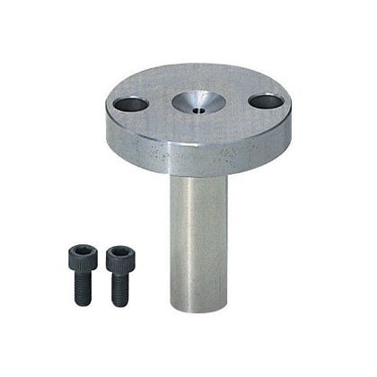 A-Type Sprue Bushing
A-Type sprue bushings are available with a D dimension of 40 mm, D1 of 35 mm, and T of 20 mm. The catalog provides internal diameter options of d = 8, 10, 12, 16, and 20 mm, with corresponding d1 and d2 dimensions. Available lengths range from 30 to 200 mm. Custom dimensions can also be manufactured according to customer drawings.
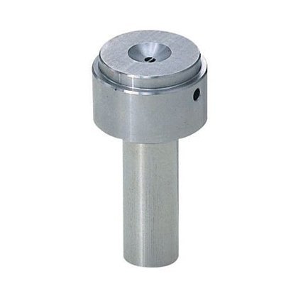 B-Type Sprue Bushing
B-Type sprue bushings are specified with D = 30 mm and T = 15 mm. The available internal diameter options include d = 8, 10, 12, 16, and 20 mm, with corresponding d1 and d2 dimensions shown in the dimensional table. Standard lengths are available within the catalog range of 30–200 mm, with custom dimensions available for drawing-based requirements.
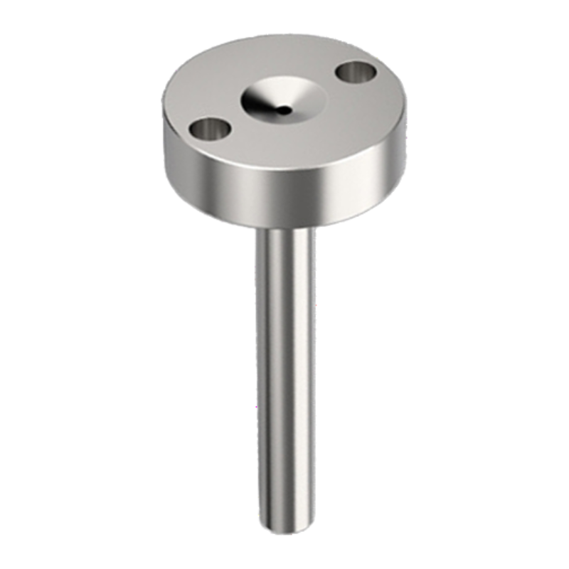 C-Type Sprue Bushing
C-Type sprue bushings use a different dimensional configuration, with D options of 35, 40, and 50 mm. The catalog specifies T values of 10 or 15 mm, internal diameter options of 10, 12, 16, and 20 mm, and a 3° angle. Depending on the configuration, the catalog provides L ranges of 50–120 mm or 50–150 mm.
C-Type also includes a B dimension of 25, 30, or 36 mm depending on the D configuration.
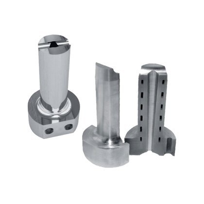 Cold Runner Sprue Bushing
Used in traditional cold runner mold systems. Its structure is simple and stable, easy for maintenance, and it is compatible with standard A, B, and U series mold bases.
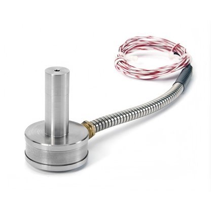 Heated Sprue Bushing
Used in molds equipped with temperature control systems, it maintains the plastic in the runner at an optimal temperature, ensuring more stable flow and preventing waste due to cooling.
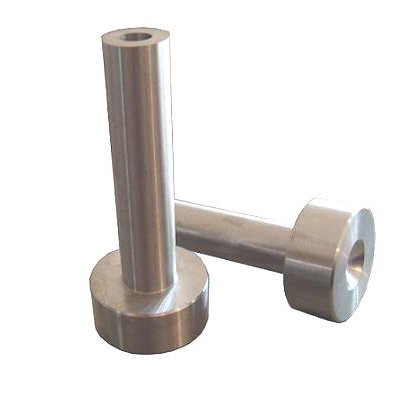 U Series Sprue Bushing
Particularly suited for small or high-precision mold designs, its small form factor occupies minimal space, making it the best choice for precision applications.
Sprue Bushing Applications
As a core component of injection molds, sprue bushings are widely used in the production of plastic products.

Used in manufacturing structural parts such as dashboards and bumpers.

Ensures surface finish quality, and meets thin-wall molding requirements.

Withstands long-term continuous operation, extending mold service life.

Endures repeated heating and cooling, effectively shortening molding cycles.
How Does a Sprue Bushing Work in an Injection Mold?
Injection Nozzle Contact
The front end of the sprue bushing forms the contact interface with the injection molding machine nozzle. The nozzle and bushing must match correctly to maintain proper contact during injection and minimize melt leakage.
Melt Entry Through the Sprue Inlet
During injection, molten plastic enters the sprue bushing through the nozzle-side inlet. The inlet geometry guides the melt into the internal passage of the bushing before it reaches the mold’s sprue and runner system.
Controlled Melt Flow Through the Bushing
The internal passage provides a controlled path for molten plastic as it travels from the injection nozzle toward the mold runner system. Internal dimensions and surface condition can affect flow behavior, so the passage must be machined accurately for the intended mold design.
Connection to the Mold Runner System
After passing through the sprue bushing, the molten plastic continues into the mold’s sprue and runner system before reaching the mold cavities.
Mounting and Alignment in the Mold
The rear portion of the sprue bushing provides the locating and mounting features needed to position the component in the mold. Proper mounting keeps the bushing aligned with the mold and injection nozzle during repeated molding cycles.
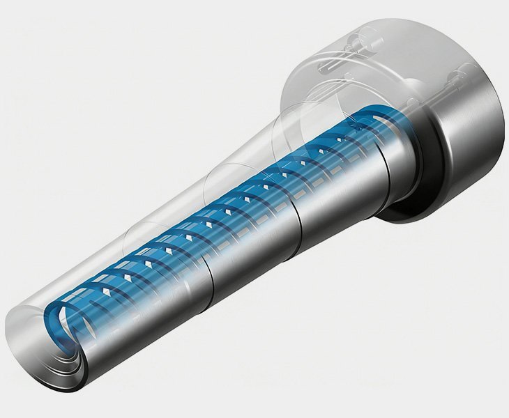
Materials and Heat Treatment Processes
We select premium alloy tool steels, such as high-strength tool steel, to ensure the sprue bushing’s wear resistance and thermal stability. For optimal performance, heat treatment strengthening is available, with custom hardness levels tailored to your requirements.
In machining, we employ precision grinding to control surface quality while polishing the inner bore to ensure smooth plastic flow. All products undergo strict concentricity tolerance control. This ensures precise alignment between the sprue bushing and injection nozzle after installation, guaranteeing reliable sealing and preventing material leakage.
Custom Manufacturing Capabilities
HTX Precision supplies A-Type, B-Type, and C-Type sprue bushings. The appropriate type is selected according to the required dimensional configuration and mold design. Standard catalog sizes are available, while non-standard dimensions can be manufactured from customer drawings.
In addition to our standard product lines, we offer custom solutions to meet your specific requirements. Whether it involves custom diameters, lengths, or nozzle-angle designs, we can manufacture to your drawings. We can utilize specialty steel materials and upgrade surface treatment processes.
In short, we will follow your specified dimensions and drawings, ensuring the final product perfectly meets your requirements and delivers both functionality and durability.
Sprue Bushing
Sprue Bushing Features
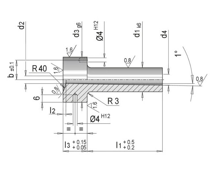
HTX Precision offers A-Type, B-Type, and C-Type sprue bushings in a range of standard dimensional configurations. The dimensions below are selected specifications from our current product catalog; non-standard sizes can also be manufactured according to customer drawings. All dimensions are in millimeters unless otherwise specified.
- Quick Comparison
- A-Type Sprue Bushing Dimensions
- B-Type Sprue Bushing Dimensions
- C-Type Sprue Bushing Dimensions
| Dimension / Feature | A-Type | B-Type | C-Type |
|---|---|---|---|
| L | 30–200 | 30–200 | 50–120 / 50–150 |
| D | 40 | 30 | 35 / 40 / 50 |
| D1 | 35 | — | — |
| T | 20 | 15 | 10 / 15 |
| d | 8 / 10 / 12 / 16 / 20 | 8 / 10 / 12 / 16 / 20 | 10 / 12 / 16 / 20 |
| d1 | 6 / 7.2 / 8 / 9.5 / 10 | 6 / 7.2 / 8 / 9.5 / 10 | — |
| d2 | 3.2 / 3.5 | 3.2 / 3.5 | — |
| SR | According to size | According to size | 3.0 / 3.5 |
| B | — | — | 25 / 30 / 36 |
| R Angle | — | — | 3° |
| L (mm) | D (mm) | D1 (mm) | T (mm) | d (mm) | d1 (mm) | d2 (mm) |
|---|---|---|---|---|---|---|
| 30–200 | 40 | 35 | 20 | 8 | 6 | 3.2 |
| 30–200 | 40 | 35 | 20 | 10 | 7.2 | 3.5 |
| 30–200 | 40 | 35 | 20 | 12 | 8 | 3.5 |
| 30–200 | 40 | 35 | 20 | 16 | 9.5 | 3.5 |
| 30–200 | 40 | 35 | 20 | 20 | 10 | 3.5 |
| L (mm) | D (mm) | T (mm) | d (mm) | d1 (mm) | d2 (mm) |
|---|---|---|---|---|---|
| 30–200 | 30 | 15 | 8 | 6 | 3.2 |
| 30–200 | 30 | 15 | 10 | 7.2 | 3.5 |
| 30–200 | 30 | 15 | 12 | 8 | 3.5 |
| 30–200 | 30 | 15 | 16 | 9.5 | 3.5 |
| 30–200 | 30 | 15 | 20 | 10 | 3.5 |
| D (mm) | T (mm) | d (mm) | SR (mm) | B (mm) | R Angle | L (mm) |
|---|---|---|---|---|---|---|
| 35 | 10 | 10 | 3.0 | 25 | 3° | 50–120 |
| 35 | 10 | 12 | 3.0 | 25 | 3° | 50–120 |
| 35 | 10 | 16 | 3.0 | 25 | 3° | 50–150 |
| 35 | 10 | 20 | 3.5 | 25 | 3° | 50–150 |
| 40 | 10 | 10 | 3.0 | 30 | 3° | 50–120 |
| 40 | 10 | 12 | 3.0 | 30 | 3° | 50–120 |
| 40 | 10 | 16 | 3.0 | 30 | 3° | 50–150 |
| 40 | 10 | 20 | 3.5 | 30 | 3° | 50–150 |
| 40 | 15 | 10 | 3.0 | 30 | 3° | 50–120 |
| 40 | 15 | 12 | 3.0 | 30 | 3° | 50–120 |
| 40 | 15 | 16 | 3.0 | 30 | 3° | 50–150 |
| 40 | 15 | 20 | 3.5 | 30 | 3° | 50–150 |
| 50 | 15 | 10 | 3.0 | 36 | 3° | 50–120 |
| 50 | 15 | 12 | 3.0 | 36 | 3° | 50–120 |
| 50 | 15 | 16 | 3.0 | 36 | 3° | 50–150 |
| 50 | 15 | 20 | 3.5 | 36 | 3° | 50–150 |
How to Choose the Right Sprue Bushing?
You need to to confirm nozzle interface / contact geometry。
Make sure the measurement of L / D / D1 / T / B, and also the measurement for fitting.
Confirm the measurement of d / d1 / d2, and also the requirements of the drawing.
Match against your drawings and actual structural dimensions.
If none of the types can meet your requirements, please send your drawing, and we can customize the sprue bushings according to your request.
The most important thing include: mold base dimensions, injection machine nozzle type, installation space, production cycle, and whether the mold uses a cold runner or heating system. Consult our professional team for guidance.
It directly affects melt sealing, positioning accuracy, pressure transfer, and the overall stability at the cavity inlet.
Yes. Properly polished internal passages reduce flow resistance, enhancing material delivery efficiency.
Heated types are typically used when strict temperature stability is demanded, such as for specific engineering plastics or flow control applications.
Yes, but you need to choose the appropriate material and heat treatment processes 1st , ensure their wear resistance and thermal stability.
The B Series is designed for general-purpose injection molding with standard wear resistance (HRC 50-52). The U Series features enhanced hardness (HRC 52-55) and is optimized for high-cycle precision molding applications where longer tool life is critical.
Sprue Bushing Technical Specifications:
| Item | Description |
| Material | Hardened tool steel |
| Application | Injection mold |
| Function | Melt flow guidance |
| Surface treatment | Precision grinding |
| Customization | Drawing-based manufacturing |